


 Spanish
 Russian
 Arabic


Products Description
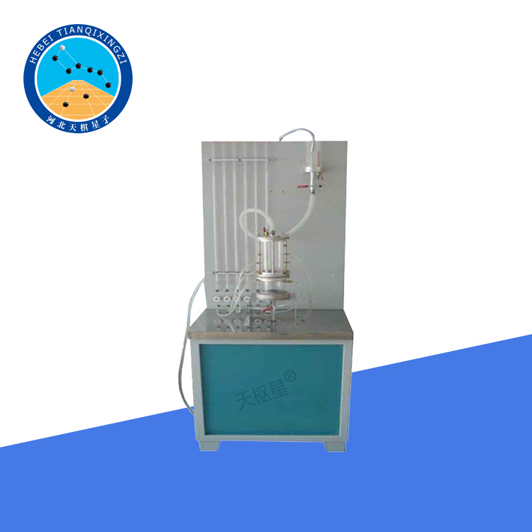
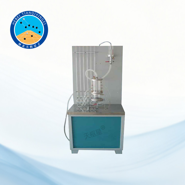
The Geosynthetic Gradient Ratio Clogging Tester is suitable for filter layer testing of geosynthetic materials. It is used to determine the permeability coefficient and permeability ratio of the soil-geotextile system and its interface under specified water flow conditions, as well as the mud content retained in the geotextile. The test results are used to evaluate whether a geosynthetic material, when used as a filter layer for a particular soil, is likely to cause unacceptable clogging.
Geosynthetic Gradient Ratio Clogging Tester
Model: TD1145-1
I. Product Introduction
The Geosynthetic Gradient Ratio Clogging Tester is developed and manufactured by Hebei Tianqixingzi Inspection Equipment Co., Ltd. in accordance with JTG E50-2006 Test Methods for Geosynthetic Materials for Highway Engineering (T 1145-2006 Clogging Test), with reference to ASTM D5101.
The gradient ratio clogging permeability test cell features alloy materials on both sides and an organic material in the middle. It provides excellent sealing performance and allows test specimens to be installed and removed conveniently and quickly.
II. Technical Parameters
1. Test Cylinder Inner Diameter: Φ100 mm
2. Soil Sample Thickness: 100 mm
3. Screen Aperture: 6 mm
4. Test Tube Inner Diameter: 3 mm
5. Pressure Measuring Plate Graduation: 1 mm
6. Power Supply: 220 V, 50 Hz
7. Overall Dimensions: 650 × 750 × 1900 mm (L × W × H)
8. Weight: 125 kg
III. Test Procedure
1. Sampling: Take samples in accordance with the requirements of T 1101-2006.
2. Number and Dimensions of Specimens: The specimen dimensions shall be compatible with the dimensions of the permeameter. The number of specimens shall be determined according to the actual test configuration and the number of geotextile layers specified in the designed filter layer.
3. Initial Weighing: Before the test, weigh the geotextile specimen to an accuracy of 0.01 g.
4. Soil Preparation: Air-dry the soil sample and sieve it to remove particles larger than 5 mm.
5. Test Water: De-aired water shall be used for the test. The water temperature should preferably be 3–4°C higher than the room temperature.
6. Specimen Installation: Place the geotextile specimen and the screen together in the clamping device and seal them securely.
7. Loading the Soil Sample: Load the soil sample to a height of 100 mm. For loose soil samples, use a funnel to pour the air-dried soil into the permeameter and level the surface. For dense soil samples, compact the soil in layers to the specified density. During sample preparation, care shall be taken to prevent the inlet of the pressure measuring tube from becoming clogged.
8. Saturation of the Soil Sample: Introduce water through the drainage outlet pipe so that water slowly enters from the bottom of the specimen. The inlet water head can be controlled to less than 25 mm until the water level rises to a certain height above the top surface of the soil sample. Then, introduce water through the inlet pipe until the entire container is filled with water. A vacuum pump may be used to accelerate soil sample saturation.
9. Water Level Adjustment: Adjust the water level so that the hydraulic gradient i reaches 1.0, and observe the changes in the water levels in the pressure measuring tubes.
10. Start of Permeation: When the readings of all pressure measuring tubes have stabilized, maintain a constant water head in the upstream water supply container. Open the outlet valve and allow water to flow through the specimen.
11. Measurement and Recording: Measure the water levels in the pressure measuring tubes and the seepage volume once every hour. At the same time, record the seepage time and water temperature. Continue the measurements for 24 hours. If the readings have not yet fully stabilized, the measurement interval may be appropriately extended until stable readings are obtained.
12. Adjustment of Hydraulic Gradient: After completing the test at a hydraulic gradient i = 1.0, adjust the hydraulic gradient and conduct tests on the same specimen at i = 2.5, 4.0, and 10.0, respectively. After each increase in hydraulic gradient, wait until the pressure measuring tube readings have stabilized, and maintain seepage at that gradient for at least 1.5 hours. When i = 10.0 and the pressure measuring tube readings have stabilized, repeat Steps 10–11.
13. End of Test: After the test, remove the geotextile specimen and gently remove any loose soil from its surface. Dry the specimen in an oven and then weigh the total mass of the geotextile specimen and the soil retained within it, with an accuracy of 0.01 g.
IV. Test Report
The test report shall include the following:
1. Sample name, specifications, and condition description;
2. Description of sample condition;
3. Test date;
4. Permeameter specifications and main technical indicators;
5. Effective Water Flow Area of the Specimen
6. For the Determination of Overall Permeability Performance: The collection of flow velocity versus head loss curves for each specimen.
V. Key Features
1. Wide Application: Suitable for evaluating the clogging potential and filtration performance of geotextiles and other geosynthetic materials used as filter layers.
2. Gradient Ratio Testing: Supports testing under multiple hydraulic gradients, including i = 1.0, 2.5, 4.0, and 10.0, allowing comprehensive evaluation of the permeability behavior of the soil-geotextile system.
3. Reliable Sealing: The gradient ratio permeability test cell adopts alloy materials on both sides and an organic material in the middle, providing good sealing performance and minimizing water leakage during testing.
4. Convenient Specimen Installation: The clamping structure facilitates quick and convenient installation and removal of test specimens.
5. Comprehensive Evaluation: The tester can be used to determine permeability characteristics, water flow behavior, and the amount of soil retained within the geotextile, providing a basis for evaluating the clogging performance of geosynthetic filter materials.
