


 Spanish
 Russian
 Arabic


Products Description
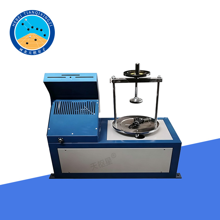
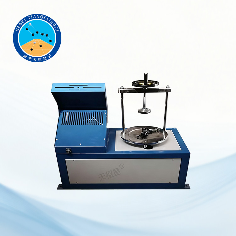
The Geotextile Apparent Opening Size Tester (Dry Sieving Method) is designed to determine the apparent opening size (AOS) of geotextiles and related geosynthetic materials using the dry sieving method. It provides reliable and repeatable test results and is suitable for laboratory quality control, material evaluation, and geotechnical engineering applications.
Geotextile Apparent Opening Size Tester | Dry Sieving Method
Model:TD1144-1
I. Product Overview
The Geotextile Apparent Opening Size Tester was developed and manufactured by our factory at the request of the National Building Materials Quality Inspection Center. After operational testing by the Quality Inspection Center, the tester was proven to have a reasonable design, with all performance indicators meeting the specified design requirements. The instrument is suitable for determining the apparent opening size (AOS) of various types of geotextile products.
Reference Standards: JTGE50, GB/T17634, ASTM D4751/D4751M, ISO 12956:2019
II. Technical Specifications
1. Supporting Screen Diameter: 200 mm
2. Horizontal Oscillation Frequency: 221 cycles/min
3. Rotational Radius: 12.5 mm
4. Vibration Frequency: 147 cycles/min
5. Vertical Vibration Amplitude: 8 mm
6. Stopwatch Range and Accuracy: 60 min ± 0.1 s
7. Spherical Glass Bead Sizes: 0.055 mm, 0.068 mm, 0.078 mm, 0.098 mm, 0.125 mm, 0.200 mm, 0.260 mm, 0.300 mm, 0.450 mm, and 0.680 mm, 300 g each
8. Optional Balance: 200 g capacity, 0.01 g readability
9. Overall Dimensions: 680 × 420 × 750 mm
10. Weight: 100 kg
III. Main Structural Description
The machine mainly consists of a base, upper cover, rotary mechanism, vibration mechanism, clamping mechanism, and special sieves for apparent opening size testing. The main structural components are described as follows:
1. Rotary Mechanism
The motor drives the transmission shaft and the gear on the rotating sleeve of the clutch mechanism. Through gear transmission, the small bevel gear on the gear shaft is driven to rotate. The small pinion then drives the large pinion, causing the hollow main eccentric shaft connected to it by a key to rotate. This, in turn, drives the three auxiliary eccentric shafts evenly distributed at 120° intervals on the upper cover to rotate, causing the entire movable frame to perform a circular planar oscillating motion with a radius equal to the eccentricity.
2. Vibration Mechanism
When the movable frame performs circular planar oscillation, the main eccentric upper cover, which is fixed to the frame with screws, drives the impact shaft to rotate. This causes the upper-end cam on the impact shaft to rotate. At the same time, the gear on the gear shaft drives the small pinion through gear transmission, which in turn drives the large bevel gear. The lower-end cam connected to the bevel gear by a key rotates slowly.
The upper and lower cams rotate in the same direction, generating axial displacement and causing the impact shaft to move upward. When the shaft reaches the notch between the upper and lower cams, it drops downward, thereby producing the required vibrating motion. The compression spring is used to increase the impact force.
3. Clamping Mechanism
By rotating and tightening the bolt, the retracting nut moves axially, causing the screen-cover fixing push rod to extend outward. The push rod then presses firmly against the screen-cover guide rod, thereby securing the screen cover in place.
4. Lubrication System
The lubrication system has a simple design. All bearings are lubricated with grease. The gears and the copper bushings in contact with the main and auxiliary eccentric shafts are lubricated by splash lubrication.
Spindle oil is recommended as the lubricating oil. Lubricating oil can also be added through the oil nozzle located at the eccentric shaft to ensure adequate lubrication and prevent insufficient oil coverage caused by splash lubrication.
IV. Operating Procedure
1. Remove the specimen holder (6) and lay the specimen flat and evenly on the supporting screen (18) without applying excessive force. Secure the specimen firmly with the specimen holder, ensuring that the specimen remains horizontal.
2. Evenly distribute the particle material selected according to the applicable standard over the surface of the specimen.
3. Connect the power supply and turn on the power switch (15).
4. Set the test duration on the timer (17). According to GB/T 17634-1998, the test duration can be set to 600 seconds. The timer has two timing ranges: 0–99.99 s and 0–99 min 59 s.
5. Connect the water inlet (14) to a stable pressurized water supply. Place the shower head (10) inside the transparent cover (8), close the splash-proof cover, and fasten the clamp (7). Open the flow control valve (13) to spray water onto the specimen.
6. Press the Start button (16) to begin the test.
7. Collect the particles that pass through the specimen as they flow out through the collection trough (3).
8. When the preset test time is reached, stop the vibration of the instrument.
9. Collect the particle material that has not passed through the specimen, together with the specimen.
10. Process the test results in accordance with GB/T 17634-1998.
11. After completing the test, switch off the power and clean the instrument.
V. Automatic Parking Device
After the power switch of the rotary automatic parking device is turned on, the timer controls the motor to run continuously or stop at set intervals via an intermediate relay. For safe operation, the motor tray is equipped with a grounding screw; the user must ground the motor according to regulations.
VI. Operation, Use and Maintenance
Before starting the machine, remove the upper oil plug and fill the lubrication oil to the level of the threaded hole. Spindle oil is recommended.
When installing the stacked sieves, first turn the tightening bolt counterclockwise to release the screen-cover fixing push rod. Then lift the screen cover together with the push rod. Turn the bolt clockwise to secure it, place the stacked sieves on the tray, then loosen the tightening bolt, press the screen cover downward, and turn the bolt clockwise to secure the sieves firmly before operation.
According to the operating requirements, turn the control knob to the continuous operation position when continuous operation is required. For timed operation, turn the knob to the desired timing position. If the machine needs to be stopped during operation, switch off the power supply and allow the timer to return automatically to the stop position. Do not force the timer knob back manually.
The machine is easy to maintain. Replace the spindle oil every 3–6 months. During operation, take care to prevent deformation of the two guide rods on the cover plate.
The instrument must be protected from moisture and corrosion. After approximately two years of use, the machine should be thoroughly cleaned and lubricated.
VII. Precautions
1. This instrument operates at a certain frequency; the worktable must be isolated from other equipment.
2. If sand is used as the test particles, please ensure the instrument is kept clean.
3. After the test, please drain all water and debris from the instrument.
4. The eccentric shaft, support spring, and other moving parts should be lubricated regularly.
