


 Spanish
 Russian
 Arabic

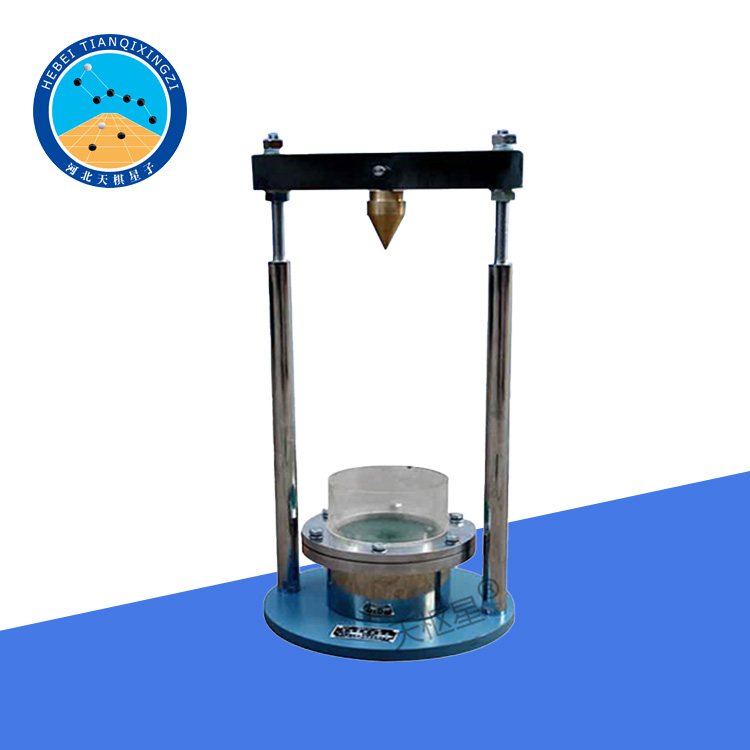

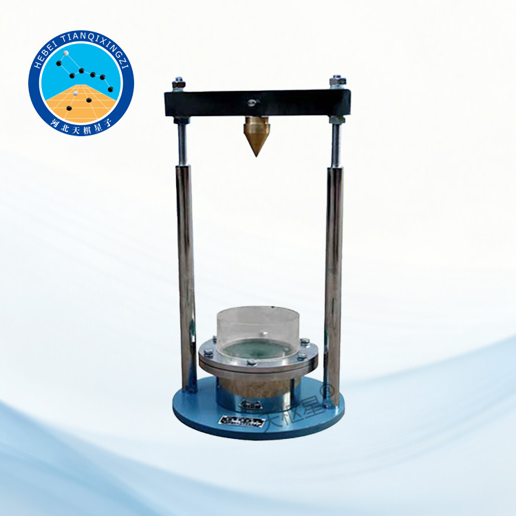
Products Description
The Geosynthetics Dynamic Cone Drop Test Apparatus is designed to evaluate the dynamic perforation resistance of geotextiles and related geosynthetic materials. A stainless-steel cone is dropped from a specified height onto the specimen to simulate impact from sharp objects and determine the resulting penetration. The apparatus is suitable for laboratory testing of geotextiles and other geosynthetics in accordance with ISO 13433 and relevant test methods.
Geosynthetics Dynamic Cone Drop Test Apparatus
Model:TD1128-1
I. Product Overview
This apparatus is designed to determine the resistance of geotextiles and related products to penetration by a steel cone dropped from a specified height. It evaluates the degree of damage caused to the geotextile when sharp stones or similar objects impact its surface. The performance of the apparatus complies with the requirements of GB/T 17630-1998, Geotextiles and Related Products—Dynamic Perforation Test—Cone Drop Method, with reference to the apparatus requirements specified in ISO 13433.
II. Test Principle
The geotextile specimen is horizontally clamped between the clamping rings. A stainless-steel cone of specified mass is dropped onto the specimen from a height of 500 mm. The impact of the falling cone creates a hole in the specimen. A small graduated measuring cone is then inserted into the hole to determine the degree of penetration.
III. Main Technical Parameters
1. Inner Diameter of Clamping Ring: 150 ± 0.5 mm
2. Distance from Cone Tip to Specimen: 500 ± 2 mm
3. Stainless-Steel Cone: Maximum diameter φ50 mm; cone angle 45°; total mass 1000 ± 5 g (including guide rod)
4. Graduated Measuring Cone: Mass 600 ± 5 g; graduation value φ2 mm/division
5. Overall Dimensions: 435 × 575 × 1600 mm
6. Instrument Weight: 55 kg
IV. Instrument Structure
The instrument mainly consists of a frame, a free-fall device for the steel cone, and a clamping ring.
1. Frame: Rigidly connected by components such as 1) a base, 2) a column, 3) a top plate, and a central beam.
2. The base has four adjustable feet. By adjusting these feet, the bubble in the leveling bubble is centered, ensuring the instrument is level.
3. Clamping Ring: The clamping ring is a flange-type clamping ring, secured with eight bolts for sample clamping.
4. Free-Fall Steel Cone Device
The end of the steel cone is connected to a guide rod and mounted on the machine. Guide holes are provided in both the intermediate beam and the top plate of the frame to ensure that the cone can fall freely without affecting its falling speed. The intermediate beam is also equipped with a locking handle.
The steel cone is raised to a height of 500 mm above the specimen and then released to fall freely, creating a perforation in the specimen. A metal protective cover and a transparent outer shield are installed below the intermediate beam. After the specimen is securely clamped, the transparent outer shield is pulled down, and the handle is then operated to release the steel cone.
After the steel cone has fallen, the transparent outer shield can be pushed upward until it reaches the latch of the protective cover, where it automatically locks into position for convenient operation.
V. Operating Procedure
1. Install the apparatus on a stable and solid foundation, and level the apparatus according to Section 4.1.
2. Raise the steel cone to the upper position and secure it in the locked position.
3. Push up the transparent protective shield and securely clamp the specimen in the clamping ring, ensuring that the specimen is free of wrinkles.
4. Lower the transparent protective shield and release the locking handle. The steel cone then falls freely from a height of 500 mm onto the specimen.
5. Immediately raise the steel cone to the position described in section 5.2. Allow the cone to descend under its own weight until it enters the hole. Read the measurement data after 10 seconds.
6. Repeat sections 5.3-5.5 until all specified samples have been tested.
7. Process the test results according to GB/T 17630-1998 standard.
VI. Precautions
1. For safety, ensure the steel cone is locked each time it is in the upper position.
2. To ensure the steel cone falls freely, the guide hole must be free of debris.
3. Lower the transparent protective cover before dropping the steel cone.
4. To avoid damaging the tip of the steel cone, do not test it on hard objects.
