


 Spanish
 Russian
 Arabic

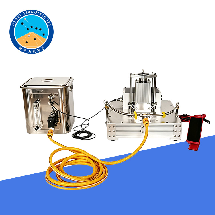

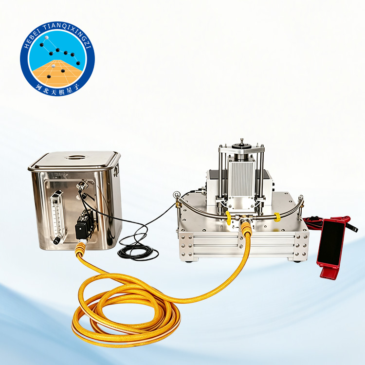
Products Description
The Dynamic Friction Tester (DFT) for Pavement Testing is a professional instrument designed to measure pavement surface friction characteristics and dynamic friction coefficients. It complies with ASTM E1911 and JTG 3450 standards, providing accurate friction data for asphalt pavements, concrete roads, and other surfaces. With real-time data recording and graphical analysis, it is widely used for pavement skid resistance evaluation, road safety research, and surface friction testing.
Dynamic Friction Tester (DFT) for Pavement Testing
Model: TD968-1
I. Product Introduction
The Dynamic Friction Tester is used to measure the dynamic friction coefficient between two sliding contact surfaces. During the measurement process, the test data can be recorded and displayed in graphical form simultaneously.
The tester complies with the Chinese industry standard JTG 3450-2019 “Field Test Methods of Subgrade and Pavement for Highway Engineering” and the American standard ASTM E1911-2009 “Standard Test Method for Measuring Paved Surface Frictional Properties Using the Dynamic Friction Tester.” In addition to road surfaces, this system can also be used to measure the friction characteristics of floors in buildings and sports halls, narrow corridors, bus entrances and exits, table surfaces, and other similar surfaces.
II. Product Features
1. The test value is a continuous dynamic friction coefficient curve that varies randomly with speed, exhibiting excellent repeatability.
2. High testing speed; testing and data recording are completed simultaneously in a very short time.
3. This instrument consists of two compactly designed components, which can be transported in a small car.
4. Despite its small size, this dynamic friction coefficient measuring instrument can simulate actual speeds and loads applied to the road surface by common motor vehicles, and the measured data closely matches reality.
5. This instrument is powered directly from a car battery (DC 12V).
6. No special skills are required, and the measurement data is unaffected by operator differences.
7. The dynamic coefficient of friction at each speed (maximum speed up to 80km/h) can be read from a continuous curve.
8. The standard test rubber pad is made of the same material as the tires of the friction test vehicle, and the test pad is easy to replace.
9. Equipped with a large LCD screen, touch panel, and keyboard input, allowing on-site operation without the need for a computer.
10. The measured data can be stored in the data acquisition unit and transferred to a computer for further processing and analysis.
III. Technical Parameters
1. Simulated vehicle speed: 10–80 km/h; coefficient of friction at simulated vehicle speed: 0–1.
2. Contact pressure: 150 kPa
3. Slider fixing pressure: 11.8 N
4. Slider dimensions: 6 mm x 16 mm x 20 mm
5. Slider hardness: 58 ± 2 (Shore hardness)
6. Temperature Measurement: -10~100℃±1℃
7. Power Supply: DC 12V (vehicle battery)
8. Rated Power: 300W
9. Main Unit Dimensions: 550mm x 580mm x 400mm
10. Main Unit Weight: 18kg
11. Controller dimensions: 370mm x 270mm x 150mm
12. Controller weight: 4kg
13. Data evaluation: Automatically calculates the friction coefficient at different speeds; displays and prints the friction coefficient versus speed curve; displays and prints statistical and evaluation results for the test section.
IV. Test Procedure
(1) Select a relatively flat and uniform surface on the wheel track as the test point, avoiding ruts, potholes, or protrusions as much as possible. Clean the surface of the test point thoroughly. Place the dynamic rotary friction coefficient meter on the test point, ensuring the bottom drain pipe can easily drain water towards the test point.
(2) Connect a bucket filled with clean water to the instrument's inlet pipe via a water pipe. The bucket should be placed higher than the instrument. Lay the recording paper flat on the X-Y recorder as required. When using a vehicle battery, the vehicle should be at idle speed to maintain stable voltage.
(3) Turn on the power switches of the control unit and the X-Y recorder in sequence, and adjust the recording pen to the origin coordinate of the recording paper using the X and Y coordinate adjusters.
(4) Raise and rotate the test disc using the drive switch, and turn on the water supply switch to start spraying water onto the test point.
(5) When the control unit displays that the disc rotation speed reaches 90 km/h, turn off the drive switch and the water supply switch. The test disc will then descend to the road surface to begin testing, and the recording pen will begin recording on the recording paper simultaneously.
(6) As the test disk gradually stops rotating, the recording pen records on the recording paper until it returns to the origin, at which point the test ends.
(7) Perform the test three times at the same test point using the above method. The difference between the maximum and minimum values of the three test results should not exceed 0.1; otherwise, the test point should be selected again for testing.
