


 Spanish
 Russian
 Arabic


Products Description
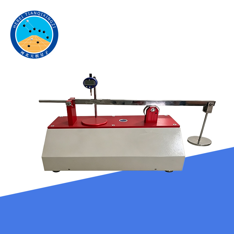
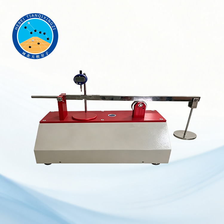
The Geosynthetic Thickness Gauge | Geotextile Thickness Tester is designed to accurately measure the thickness of geotextiles, geocomposites, and other geosynthetic materials under specified pressure. With precision loading weights, a high-resolution dial indicator, and a stable reference plate, it provides reliable thickness measurements for laboratory testing and quality control of geosynthetic materials.
Geosynthetic Thickness Gauge | Geotextile Thickness Tester
Model:TD1121-1
1. Scope of Application
This method specifies the test method for determining the thickness of geotextiles and related products under specified pressures. It is applicable to geotextiles and composite geotextiles.
2. Applicable Standards
JTG E50-2006, Test Methods for Geosynthetics Used in Highway Engineering
GB 8170, Rules for Rounding Off Numerical Values
Reference Standards: ISO 9863-1:2016, ASTM D5199
3. Technical Parameters
3.1 Dead weight of the presser foot: 5 N; applied pressure: 2 kPa
3.2 Combined weight of the presser foot + Weight A: 50 N; applied pressure: 20 kPa
3.3 Combined weight of the presser foot + Weights A, B, C, and D: 500 N; applied pressure: 200 kPa
Note: Lever ratio: 1:5
4. Test Definitions
Thickness: The distance between the two opposite surfaces of a geotextile specimen when subjected to a specified pressure.
Nominal Thickness: The thickness of a specimen measured under a pressure of 2 kPa.
5. Instrument Structure Description
5.1 Reference Plate: The area of the reference plate shall be greater than twice the area of the presser foot.
5.2 Presser Foot: The presser foot has an area of 25 cm² and a weight of 5 N, applying a pressure of 2 kPa ± 0.01 kPa to the specimen.
5.3 Weights: The total weight of the weights for nominal thickness measurement is 500 N.
5.4 Dial Indicator: Minimum graduation: 0.01 mm.
5.5 Stopwatch: Minimum graduation: 0.1 s. (Not included; user-supplied.)
6. Test Procedure
1) Sampling:
Take samples in accordance with the relevant requirements of T1101-2006 in JTG E50-2006, Test Methods for Geosynthetics Used in Highway Engineering.
2) Conditioning and Moisture Conditioning of Test Specimens:
Condition the test specimens in accordance with the requirements specified in Clause 5 of T1101-2006 in JTG E50-2006, Test Methods for Geosynthetics Used in Highway Engineering.
3) Preparation of Test Specimens:
In addition to complying with the relevant requirements of T1101-2006, cut 10 representative specimens. The size of each specimen shall be no smaller than the area of the reference plate.
4) Determination of Nominal Thickness Under a Pressure of 2 kPa:
Clean the reference plate and the 5 N presser foot, place the presser foot on the reference plate, and adjust the dial indicator to zero.
Lift the 5 N presser foot and place the specimen naturally and flat between the reference plate and the presser foot. Gently lower the presser foot so that a pressure of 2 kPa ± 0.01 kPa is applied to the specimen. Lower the contact tip of the dial indicator until it touches the specimen, then start the stopwatch. Take the reading after 30 s, with an accuracy of 0.01 mm.
Repeat the above procedure to complete the test for all 10 specimens.
If required, select the appropriate weights to apply a pressure of 20 kPa ± 0.1 kPa, and determine the specimen thickness under a pressure of 20 kPa ± 0.1 kPa.
If required, select the appropriate weights to apply a pressure of 200 kPa ± 1 kPa, and determine the specimen thickness under a pressure of 200 kPa ± 1 kPa.
7. Test Results
1) Calculate the arithmetic mean thickness δ of the 10 specimens measured under the same pressure, expressed in millimeters. Calculate the result to three decimal places and round it to two decimal places in accordance with GB 8170.
2) If required, calculate the standard deviation σ and coefficient of variation CV. The standard deviation σ and coefficient of variation CV shall be calculated in accordance with the requirements of T1102-2006 of this specification.
8. Test Report
The test report shall include the following information:
(1) Name and specifications of the test specimens;
(2) Pressure applied during the test and dimensions of the presser foot;
(3) Test results;
(4) Atmospheric conditions during the test;
(5) Test date and test personnel;
(6) Any information required to be reported according to the test procedure;
(7) A detailed description of any deviations from the specified test procedure.
