


 Spanish
 Russian
 Arabic



Products Description
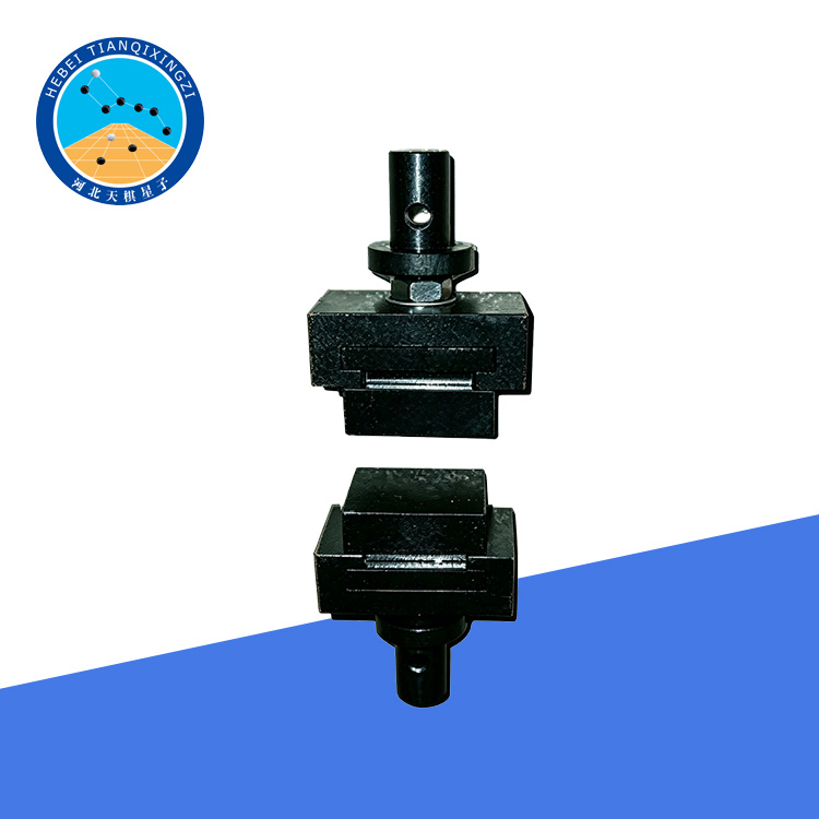
This fixture is designed for precise bonding strength evaluation of wood-based panels. It is used to securely hold test specimens and transfer uniform tensile load during testing, ensuring stable alignment and consistent force application until failure occurs. The structure provides high rigidity and accurate positioning, making it suitable for laboratory and quality control testing of composite wood materials.
Internal Bond (IB) Strength Test Fixture for Wood-Based Panels
Model: TD17657-ZJ
I. Product Introduction
The Internal Bond Strength Test Fixture for decorative wood-based panels is developed by our company in accordance with the technical requirements specified in GB/T17657. This product is suitable for internal bond strength testing of non-decorated particleboard, fiberboard, cement-bonded particleboard, and wood-based panels without veneer surface decoration.
Applicable or Referenced Standards:
EN 319, ASTM D1037, ISO 16984, GB/T17657
II. Technical Parameters
Applicable Specimen: 50*50mm
III. Test Procedure for Internal Bond Strength of Decorative Wood-Based Panels
1. Specimen Preparation
Prepare test specimens according to the testing requirements.
Specimen size: 50 × 50 mm
2. Milling of Specimen Groove
A circular groove shall be milled on the surface of the specimen using a milling cutter.
* Inner diameter of groove: 35.7 ± 1 mm(circular area approximately1000 mm²)
* For non-decorated specimens: groove depth 0.13 ± 0.1 mm
* For decorative specimens: the cutting must penetrate the decorative layer, but the depth into the substrate shall not exceed 0.3 mm
After milling, the specimen surface shall be lightly sanded with sandpaper and all dust shall be removed.
3. Conditioning of Specimens
If necessary, place the specimens in an environment with:
* Temperature: 20 ± 2°C
* Relative humidity: 65 ± 5%
Condition until constant mass is achieved.
Two weighings shall be performed 24 hours apart. The specimen is considered to have reached constant mass when the difference between the two measurements does not exceed 0.1% of the specimen mass.
4. Testing Method
4.1 Bonding of Test Fixtures
Apply epoxy resin adhesive or molten hot-melt adhesive evenly on the surface of the special loading fixtures, and bond them to the circular surface of the specimen. Prevent adhesive from flowing into the groove.
Bonding pressure: 0.1 MPa – 0.2 MPa
If the heating process of hot-melt adhesive negatively affects surface bonding strength (e.g., dry-process fiberboard or certain decorative panels), cold-curing epoxy adhesive shall be used instead.
Note:If adhesive overflows into the groove, it should be cut along the groove line using a knife to separate the overflowed adhesive from the fixture.
4.2 Reinforcement for Thin Specimens
If specimen thickness is 10 mm < t < 15 mm, a square steel plate (50 × 50 mm, thickness 10 mm) shall be bonded to the back of the specimen using epoxy or hot-melt adhesive for reinforcement.
If specimen thickness is ≤ 10 mm, in addition to the back steel plate, a square steel spacer (50 × 50 mm, thickness 2–3 mm) with a central hole of 40 mm diameter shall be placed between the specimen and the fixture.
4.3 Loading and Testing
Install the specimen onto the testing machine using the fixture assembly as shown in Figure 18 (not included).
* Load shall be applied uniformly
* Time to failure: 60 ± 30 seconds from the start of loading
* Record the maximum load value with accuracy of 1 N
4.4 Test Validity
If failure occurs at the adhesive layer between the fixture and the specimen, the result is invalid and a new specimen shall be taken from the same panel for retesting.
5. Test Results Calculation
5.1 Calculation Formula
The surface bonding strength is calculated using the following formula:
σzj = Fmax / A
Where:
σzj = surface bonding strength (MPa)
Fmax = maximum load at failure (N)
A = bonding area between specimen and fixture (A = 1000 mm²)
5.2 Result Expression
The surface bonding strength of a panel shall be the arithmetic mean value of all specimens taken from the same panel.
Final result shall be expressed in MPa, accurate to 0.01 MPa.
